555 Timer Schematic Diagram - Electronics Components Double Up With The 556 Dual Timer Dummies. The schematic shown below is a 555 timer circuit. Although the schematic looks correct, this basic circuit may actually have a few negative aspects. Working modes of 555 timer ic. Receiving single trigger for the start of timing is sufficient. After one minute of time duration, the led will automatically turn on.
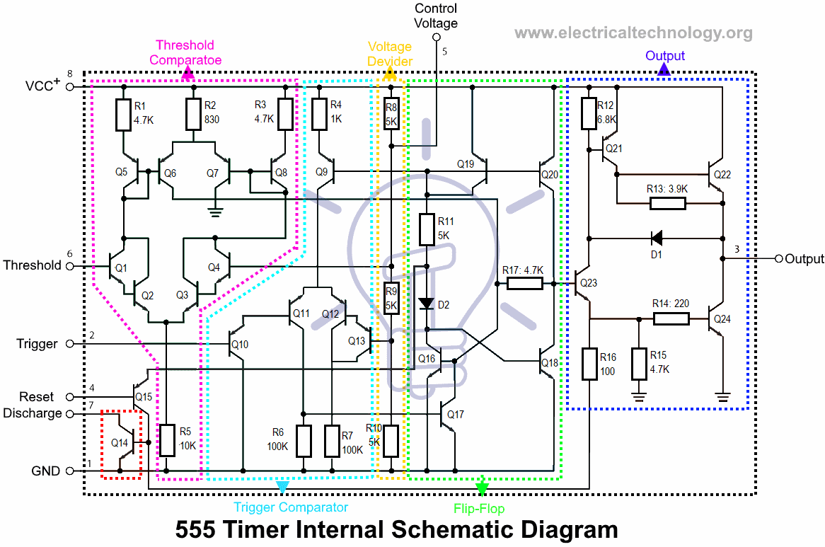
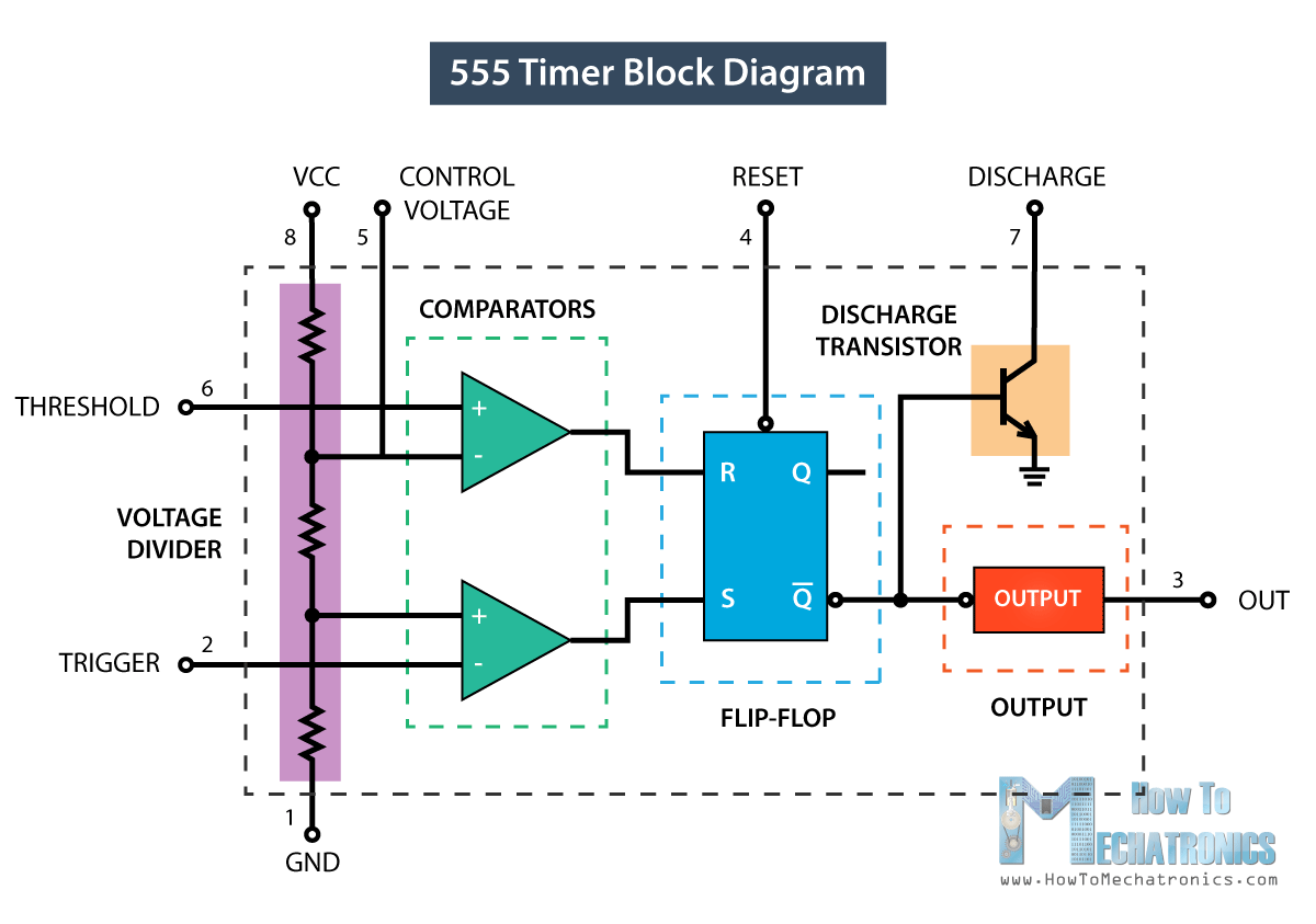
Resistive network consists of three equal resistors and acts as a voltage divider. The block diagram of a 555 timer is shown in the above figure. The 555 timer delay before turn on circuit we will build is shown below. 555 timer circuit | circuit diagram. 555 timer is an industrial standard ic existing from early days of ic.
555 Timer Ic Types Construction Working Applications from www.electricaltechnology.org The circuit mentioned here is a ten minutes timer, after pusing. The 555 timer can be obtained very cheaply from pretty much any electronic retailer. With this information you will learn how how the 555 works and will have the experience to build some of the circuits below. If you want to know all the pinout of the 555 timer, what each pin is and what each pin does, see 555 timer pinout. The 555 timer, designed by hans camenzind in 1971, can be found in many electronic devices starting from toys and kitchen appliances to even a spacecraft. The block diagram of a 555 timer is shown in the above figure. Let us discuss in detail about this circuit. This is the circuit diagram of 555 timer wired in monostable mode.
You only need a 555 timer, a few diodes (a diyode helps too), a potentiometer, as well as a few resistors and capacitors.
The reset input current draw illustrates the need for a current limiting resistor as shown in some of the preceding circuits. The 555 timer, designed by hans camenzind in 1971, can be found in many electronic devices starting from toys and kitchen appliances to even a spacecraft. If a 10uf timing capacitor is used, calculate the value of the resistor required to produce a minimum output time delay of 500ms. The second 555 timer helper will extend the timers output duration without having to use large values of r1 and/or c1. Basic 555 monostable multivibrator circuit. As the name indicates, only one state is stable and the other one is called unstable or quasi stable state. 555 timer was first introduced by signetics corporation in 1971 as se555/ne555. In monostable mode, the duration for. Figure 2 shows the basic 555 timer monostable circuit. 8 th pin and 1 st pin of the 555 timer are used to given power vcc and ground respectively. Some devices will not function properly if the current to the threshold input is not restricted. We connect a 100μf capacitor to the positive voltage supply and then to pin 2. The block diagram of a 555 timer is shown in the above figure.
The circuit mentioned here is a ten minutes timer, after pusing. Building this circuit in its simplest form is quite straight forward. The 555 timer can be obtained very cheaply from pretty much any electronic retailer. Whether it's windows, mac, ios or android, you will be able to download the images using download button. Referring to the timing diagram in figure 3, a low voltage pulse applied to the trigger input (pin 2) causes the output voltage at pin 3 to go from low to high.
How 555 Timers Work The Learning Circuit Youtube from i.ytimg.com 555 timer ic remains in stable state until the external triggering is applied. If you want to know all the pinout of the 555 timer, what each pin is and what each pin does, see 555 timer pinout. Figure 2 shows the basic 555 timer monostable circuit. 4 th pin is the reset pin of 555 timer, which is active low so it is connected to vcc to avoid accidental resets. Resistive network consists of three equal resistors and acts as a voltage divider. Working modes of 555 timer ic. Receiving single trigger for the start of timing is sufficient. The block diagram of a 555 timer is shown in the above figure.
Whether it's windows, mac, ios or android, you will be able to download the images using download button.
The breadboard schematic of the above circuit is shown below. The 555 timer ic is an integral part of electronics projects. The second 555 timer helper will extend the timers output duration without having to use large values of r1 and/or c1. A monostable 555 timer is required to produce a time delay within a circuit. 8 th pin and 1 st pin of the 555 timer are used to given power vcc and ground respectively. 555 timers are very popular in electronics. 555 timer ic remains in stable state until the external triggering is applied. Working time is determined by the 220k potentiometer and capacitor c1. 500ms is the same as saying 0.5s so by rearranging the formula above, we get the calculated value for the resistor, r as: If you are using mobile phone, you could also use menu drawer from browser. In monostable mode, the duration for. After one minute of time duration, the led will automatically turn on. The 555 timer can be obtained very cheaply from pretty much any electronic retailer.
555 timer, as the name specified, are the electronics circuits used for measuring time intervals.in this article, we will cover about 555 timers. Adjustable on off timer(using 555 astable mode) in this circuit a timer with cyclic on off operations is designed. The 555 timer ic is an integral part of electronics projects. The circuit mentioned here is a ten minutes timer, after pusing. Resistive network consists of three equal resistors and acts as a voltage divider.
555 Timer Ic Working Principle Block Diagram Circuit Schematics from howtomechatronics.com You only need a 555 timer, a few diodes (a diyode helps too), a potentiometer, as well as a few resistors and capacitors. The circuit uses a potentiometer to vary the output pwm signal from around 5% to 95% of the power supplied and uses a jumper to vary. 555 timer ic remains in stable state until the external triggering is applied. 8 th pin and 1 st pin of the 555 timer are used to given power vcc and ground respectively. Basic 555 monostable multivibrator circuit. In monostable mode, the duration for. Let us discuss in detail about this circuit. The working modes of a 555 timer are astable, bistable, and monostable.
If you are using mobile phone, you could also use menu drawer from browser.
We need to set 555 timer in monostable mode to build timer. This circuit uses the common 555 timer to create and vary the pwm signal. Although the schematic looks correct, this basic circuit may actually have a few negative aspects. It is a highly stable integrated circuit that can produce accurate time delays and oscillations. Receiving single trigger for the start of timing is sufficient. The circuit diagram above doesn't contain the option to use an external power supply for the output and just uses one to keep it simple. 4 th pin is the reset pin of 555 timer, which is active low so it is connected to vcc to avoid accidental resets. The 555 timer has three operating modes, bistable, monostable and astable mode. Referring to the timing diagram in figure 3, a low voltage pulse applied to the trigger input (pin 2) causes the output voltage at pin 3 to go from low to high. Figure 2 shows the basic 555 timer monostable circuit. This is the circuit diagram of 555 timer wired in monostable mode. Working time is determined by the 220k potentiometer and capacitor c1. These on off intervals can be adjusted by varying the 555 timer output and number of counter outputs.
Each mode of operation indicates a circuit diagram and its output 555 timer schematic. We connect a 100μf capacitor to the positive voltage supply and then to pin 2.

0 Comments:
Posting Komentar